About This Machine
Device Components
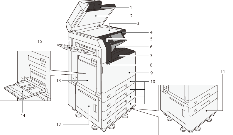
Front
No. |
Component |
Function |
|---|---|---|
1 |
Duplex Automatic Document Feeder Note
|
Load originals here. |
2 |
Document cover |
Holds an original in place. |
3 |
Document glass |
Load originals here. |
4 |
Control panel |
The touch panel display and buttons to operate the machine, and indicators to inform the machine states are located. Refer
|
5 |
Embedded IC Card Reader (optional) |
When you touch the IC Card to the IC Card reader, the machine authenticates the user. |
6 |
Exit2 Tray (Extra Center Tray) (Optional) |
Outputs are delivered here. |
7 |
Center Tray |
|
8 |
USB memory slot |
Insert the USB memory device into this slot directly. Note
|
9 |
Front door |
Open this cover to clear paper jams or replace the consumables. |
10 |
Paper Tray 1 to 4 |
Load paper here. Note
|
11 |
1 Tray Module with Cabinet (optional) |
Load paper here. |
12 |
Lower left-side door |
Open this cover to clear paper jams. |
13 |
Upper left-side Door |
|
14 |
Paper Tray 5 (Bypass) |
Load paper here. |
15 |
Left-Side Output Tray (optional) |
Outputs are delivered here. |
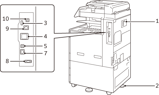
Right Side and Rear
Apeos C3567/C3067/C2567
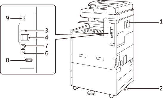
Apeos C3061/C2561/C2061
No. |
Component |
Function |
|---|---|---|
1 |
“PHONE” connector |
Use this connector when using a telephone. Note
|
2 |
“LINE1” connector |
Used for connecting a general telephone line. Note
|
3 |
“LINE2” connector (optional) |
Used for connecting a general telephone line. Note
|
4 |
“LINE3” connector (optional) |
Used for connecting a general telephone line. Note
|
5 |
Adjusting foot |
Prevents the machine from toppling over. Move the machine to its installation site and then rotate this adjuster in a clockwise direction until it touches a floor. |
6 |
USB2.0 interface connector |
Connect a memory card reader, or a USB connection option or a related product cable. |
7 |
Wireless Network Kit |
Used for connecting wireless network (Wi-Fi/Bluetooth) to the machine. |
8 |
USB2.0 interface connector |
Connects a USB cable (type B) for printing. |
9 |
USB3.0 interface connector |
|
10 |
Network port |
Connects to a network cable. |
11 |
EP interface |
Connects the device accessories such as the billing devices and authentication devices. |
12 |
Network port (optional) |
Connects to a network cable. |
13 |
USB3.0 interface connector (optional) |
Connects a USB cable (type B) for printing. |
LAN connection
When connecting to the network port, keep the machine power switched off.
Note
When a connection failure occurs, it may be improved by setting [Disabled] in
 > [Device] > [Network Settings] > [Protocol Settings] > [Ethernet Settings] > [Energy Efficient Ethernet] in the System Administrator mode.
USB connection
When connecting to a USB connector, keep the machine power switched off.
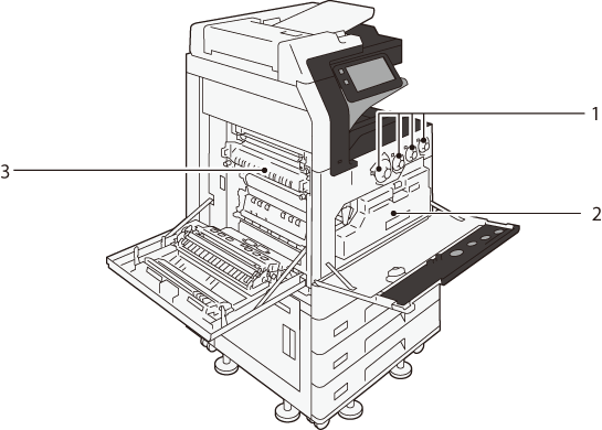
Inside
No. |
Component |
Function |
|---|---|---|
1 |
Toner Cartridges |
Contains toners of black (K), cyan (C), magenta (M) and yellow (Y). |
2 |
Waste Toner Container (R5) |
Collects waste toner. |
3 |
Fusing Unit (R8) |
Fuses toner to paper. Be careful not to touch the fusing unit due to high temperature. |
Duplex Automatic Document Feeder
Note
“Duplex automatic document feeder” is described as “document feeder” in this manual.
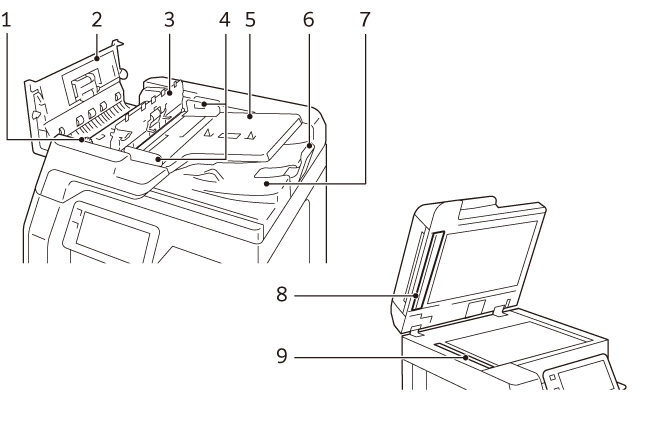
Duplex Automatic Document Feeder (3-pass duplex feeding) B1-C
No. |
Component |
Function |
|---|---|---|
1 |
Knob |
Turn this knob to clear paper jams. |
2 |
Left cover |
Open this cover to clear paper jams. |
3 |
Inner cover |
|
4 |
Document guides |
Use these guides to align the edges of originals. |
5 |
Document feeder tray |
Load originals here. |
6 |
Document stopper |
Prevents outputs from falling off. |
7 |
Document output tray |
Scanned documents are delivered here. |
8 |
Film |
Used as the background of the scanner. |
9 |
Constant velocity transport glass |
Scans a loaded original. |
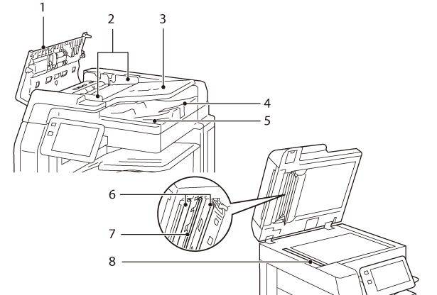
Duplex Automatic Document Feeder (1-pass duplex feeding) B5-PC/B4-PC
No. |
Component |
Function |
|---|---|---|
1 |
Left cover |
Open this cover to clear paper jams. |
2 |
Document guides |
Use these guides to align the edges of originals. |
3 |
Document feeder tray |
Load originals here. |
4 |
Document stopper |
Prevents outputs from falling off. |
5 |
Document output tray |
Scanned documents are delivered here. |
6 |
Film |
Used as the background of the scanner. |
7 |
Side 2 constant velocity transport glass |
Scans Side 2 of the loaded original. |
8 |
Side 1 constant velocity transport glass |
Scans Side 1 of the loaded original. |
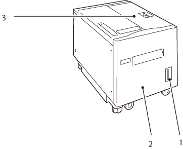
High Capacity Feeder B1 (optional)
No. |
Component |
Function |
|---|---|---|
1 |
Remaining volume display |
You can check the remaining paper volume. |
2 |
High capacity tray (Paper Tray 6) |
Load paper here. |
3 |
Top cover |
Open this cover to clear paper jams. |
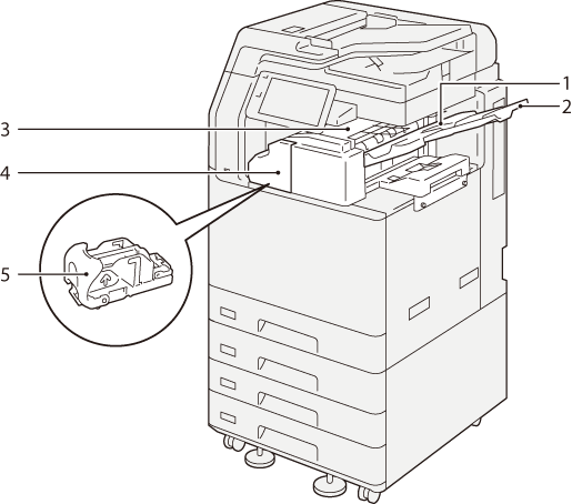
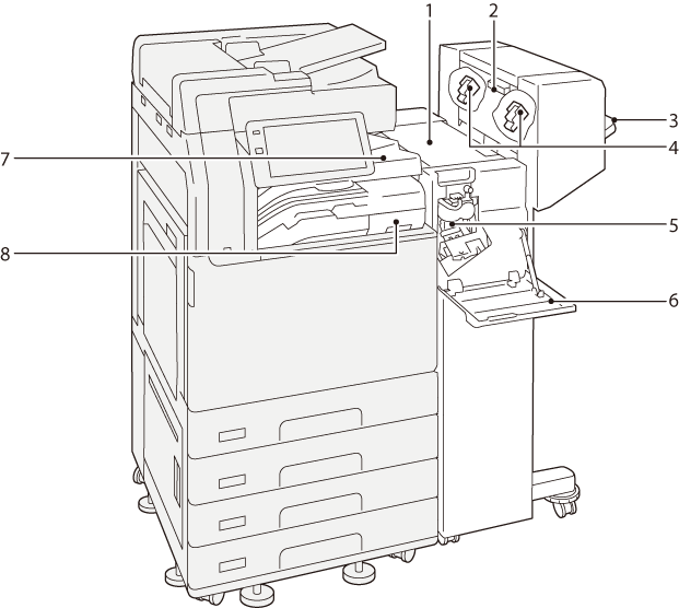
Finisher A3 (optional)
No. |
Component |
Function |
|---|---|---|
1 |
Center Tray |
Outputs are delivered here. |
2 |
Extension Tray |
This prevents the ejected paper from falling out. |
3 |
Finisher Tray |
Outputs are delivered here. The guide wire holds the output paper. |
4 |
Front door |
Open this door to clear paper jams, replace staples, or remove jammed staples. |
5 |
Staple Cartridge |
This unit is used to replace staples. |
Extension Tray
When ejecting paper in landscape orientation, pull out the Extension Tray.
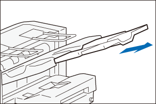
Note
Roller-shaped trace may be left on coated paper.
Finisher B (optional)
Note
In this guide, “Finisher B4”, “Finisher B5”, “Finisher B with Booklet Maker Unit”, “Finisher B with 2/4 Hole Punch Module”, and “Finisher B with US 2/3 Hole Punch Module” are generally referred to as “Finisher B”.
No. |
Component |
Function |
|---|---|---|
1 |
Top cover |
Open this cover to clear paper jams. |
2 |
Left-side door of Booklet Maker |
Open this door when replacing staples for saddle stitch. |
3 |
Finisher Tray |
Finished outputs are delivered here. |
4 |
Booklet Staple Cartridges |
This unit is used to replace staples for saddle stitch. There are two. |
5 |
Staple Cartridge (for side stitch) |
This unit is used to replace staples for side stitch. |
6 |
Front door |
Open this door to clear paper jams, replace the staple cartridge, or remove jammed staples. |
7 |
Finisher transport cover |
Open this cover to clear paper jams. |
8 |
Hole Punch Waste Container |
Punched pieces go in here. |
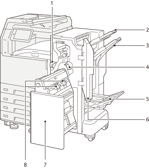
Finisher C (optional)
Note
In this guide, “Finisher C4”, “Finisher C4 with Booklet Maker Unit”, “Finisher C5”, and “Finisher C5 with Booklet Maker Unit” are generally referred to as “Finisher C”.
No. |
Component |
Function |
|---|---|---|
1 |
Hole Punch Waste Container |
Punched pieces go in here. |
2 |
Top Output Tray |
Outputs are delivered here. |
3 |
Finisher Tray |
Side-stitch stapled outputs are delivered here. |
4 |
Staple Cartridge (for side stitch) |
This unit is used to replace staples for side stitch. |
5 |
Booklet Tray*1 |
Saddle-stitch stapled outputs are delivered here. |
6 |
Front door |
Open this door to clear paper jams, replace the staple cartridge, remove jammed staples or dispose of cut pieces for punched holes. |
7 |
Booklet Maker |
This device is used to fold paper into two or staple folded paper. |
8 |
Booklet Staple Cartridges*1 |
This unit is used to replace staples for saddle stitch. There are two. |
- In case of Finisher with Booklet Maker